Shore Power Cable Storage Modification
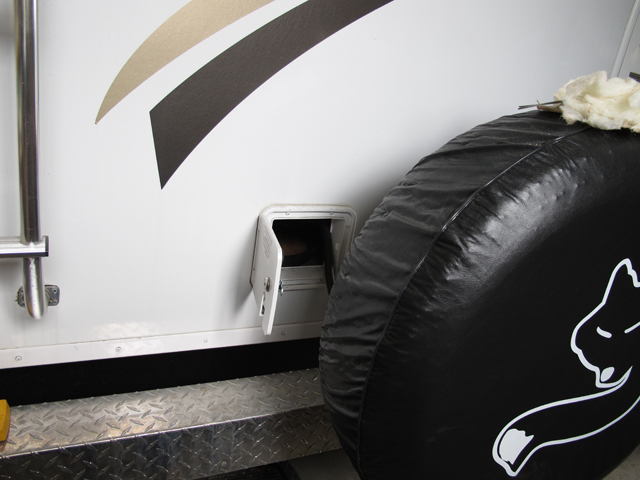
The original location for the shore power cable storage is . . . well, it's a PITA. First off, the cable is stored in a 1 foot square box in the kitchen cabinet. The 24-5N floor plan is an excellent floor plan for such a compact coach, but being compact it can't afford to waste storage space and this is one that peeved both of us. To make matters worse, the access door is located in dead center in the rear of the coach where it's blocked by the spare tire. And if that wasn't bad enough, the box that the cable is stuffed into is just too small to be convenient. It takes a bit of effort to wind the cable just right and who wants to bother?
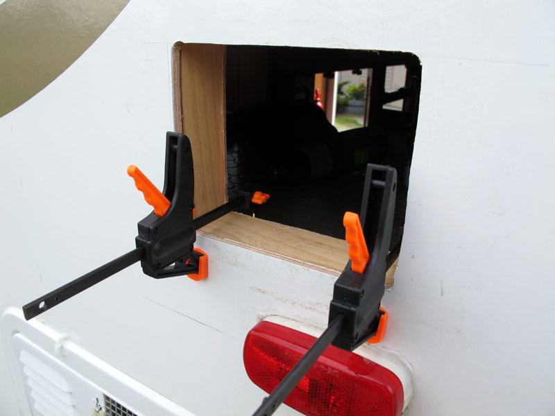
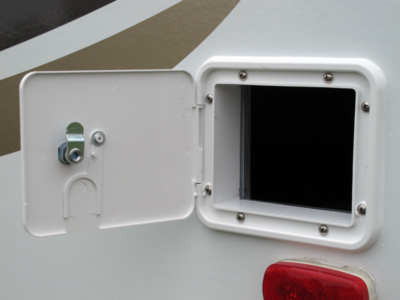
Here's a photo of the access door in the center of the rear cap.
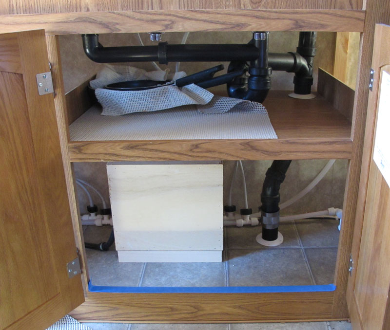
What were they thinking when they blocked off this much space in the kitchen cabinet? I guess they knew I'd need something to do & wanted to give me an obvious project.
The OE shore power cable storage box is 1' x 1' x 1'
NOTE the screws that attach the 1x2's to the floor. The one in the rear is easily visible. More on these later.

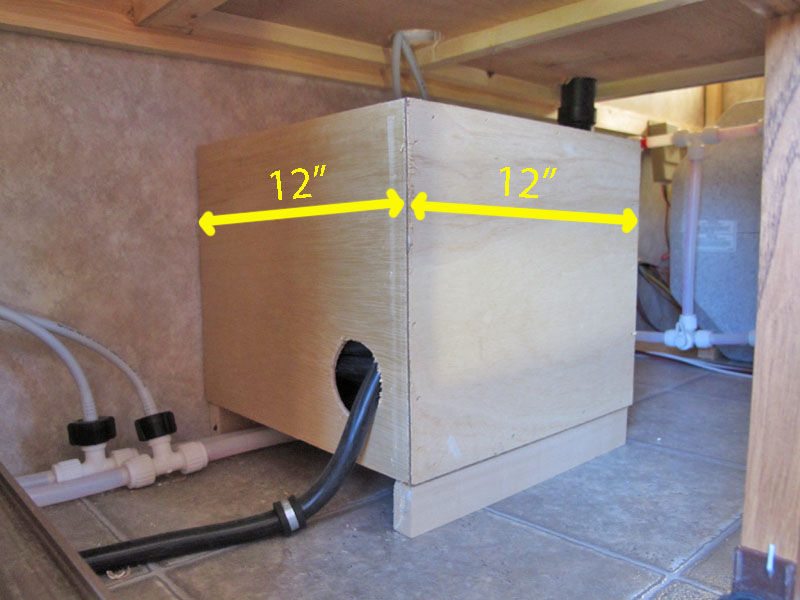
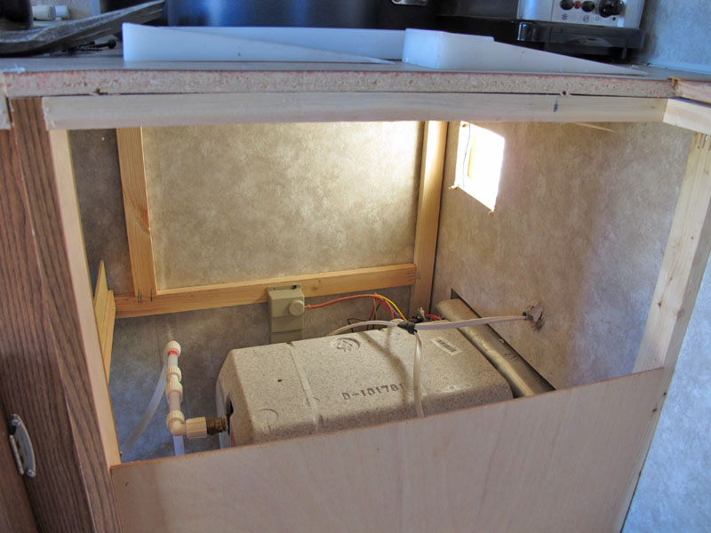
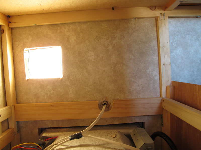
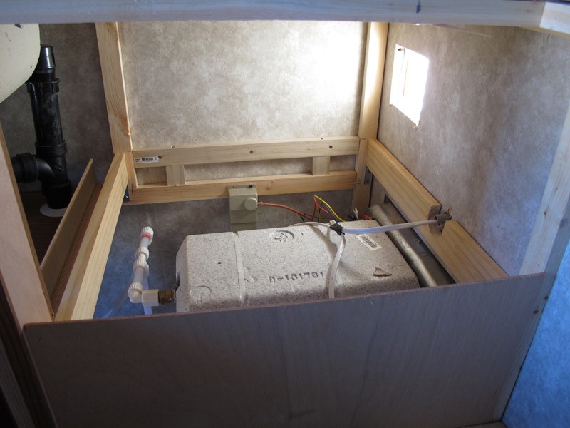
This is where I intend to relocate the shore power cable storage to - the void over the water heater. this photo was taken from the upper shelf of the cabinet.
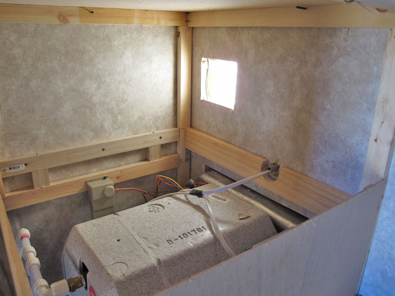
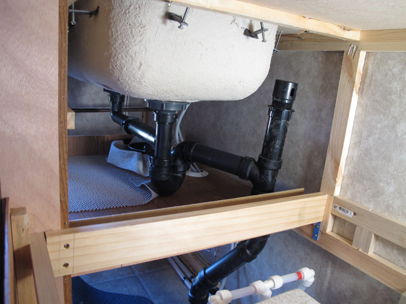
A view of the water heater from the lower shelf.
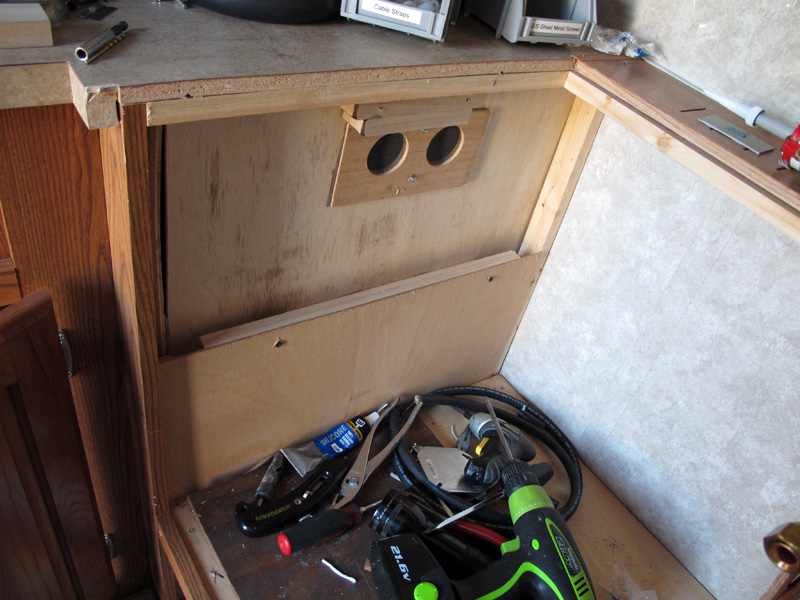
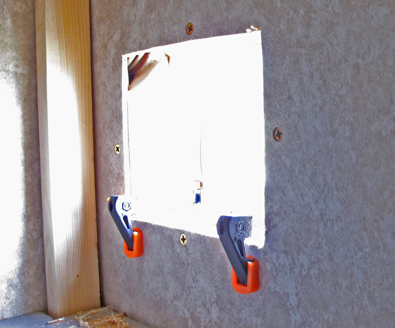
I started out by scoping out the location of the future access door. First, I scanned the wall with my stud finder. The multiple wires in the wall in this area made that a bit interesting, so I used a long & very skinny Phillips screwdriver to probe the wall space for the wall studs. I marked the exterior of the wall with masking tape to indicate where I found the vertical studs. The horizontal studs were just above the water heater and well above this photo.
My goal was to have the access door slightly above the compartment floor, but not so high that it's hard to reach. I also wanted to avoid overlapping the graphics. I've noted the distance forward from the rear molding and up from the water heater for reference.
By outlining the cut line with masking tape, I avoid scaring the finish on the exterior Filon. I started by drilling in each corner with a 1/2" brad point drill bit. I simply eye-balled the drill bit at each corner and started drilling. The nice thing about the brad point drill bit is that it cuts the finish of the Filon without ripping it. Once I had cut through the filon layer of the exterior wall, I switched to a 1/8" normal drill bit & worked up to 1/2" in several steps. Once the 1/2" holes were done, I cut out the rest of the hole with a saber saw. The saber saw blade was just long enough to cut through both the exterior and interior walls. The walls are made of a Filon layer bonded to 1/4" luan with a thinner wallboard on the interior & fiberglass insulation in the middle..
 A brad point drill bit
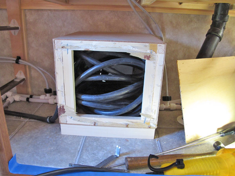
I've removed one side of the original shore power cord storage box - WOW is that cable stuffed in there! What a PITA.
Now, I've pulled the cable out of the box. Next I removed 2 of the 4 screws that attach the feet of the box to the floor. I was able to get the front screws out easily, but the rear screws didn't want to budge, so . . .
One whack with the 3# sledge and the box came loose from the rear foot.
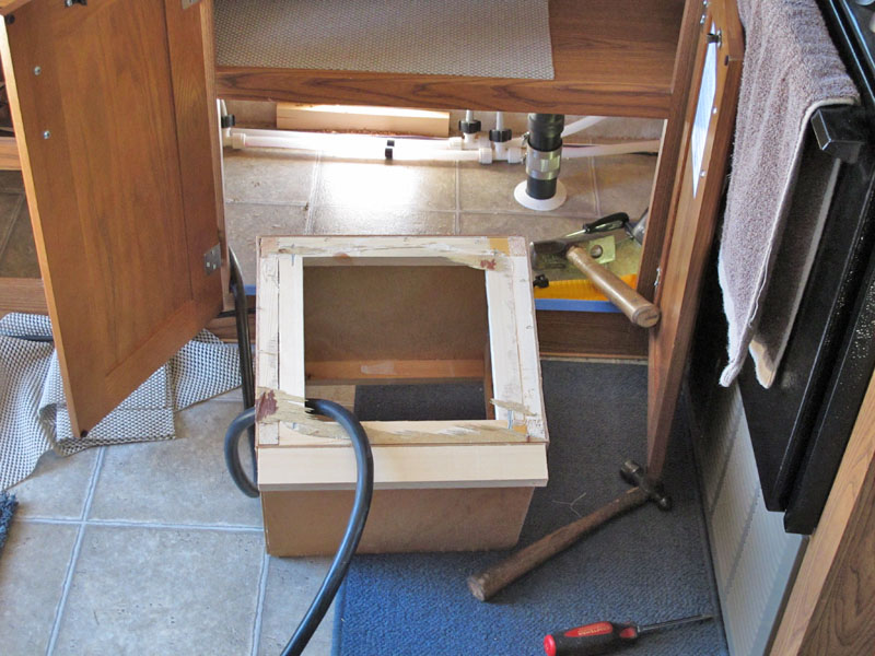
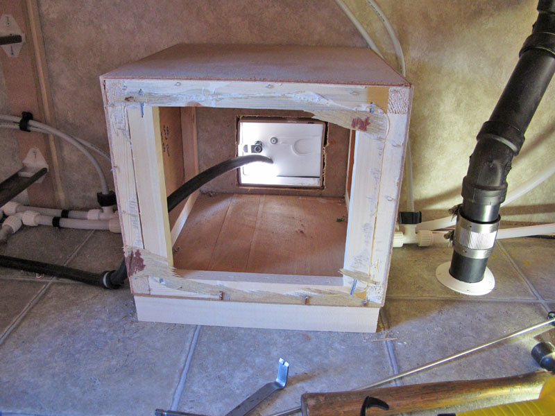
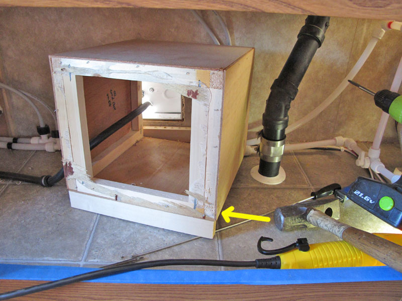
I've pulled the box out of the cabinet to fish the cable out of the box.
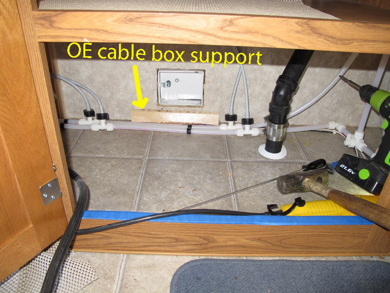
You can see the stubborn foot still securly screwed to the floor. I may build a little something to protect the plumbing and use the OE foot to support it.
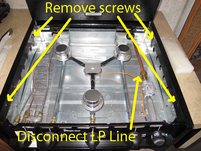
Now it's time to remove the range. First TURN OFF THE LP AT THE TANK., the disconnect the LP connection. There are 4 screws at the top as shown, and . . .
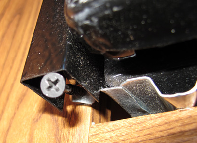
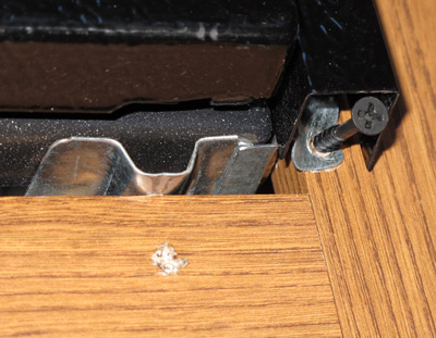
There are two screws at the bottom of the range, one on each side.
Once the LP line is safely disconnected and all 6 screws screws removed, the range can be easily slid out and lifted out of the way. Like most RV appliances, it is very light weight.
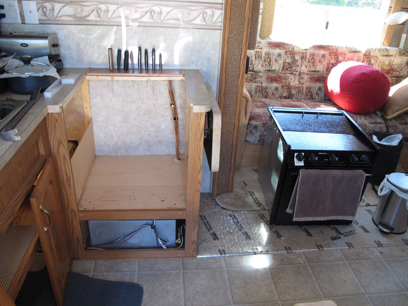
Lift the range out & set it aside. FYI, you may need to use a razor blade to slice the silicone caulk between the range and counter top for it to come out nicely.
Finally, a nice clear view of where the new shore power cord compartment is going to be.
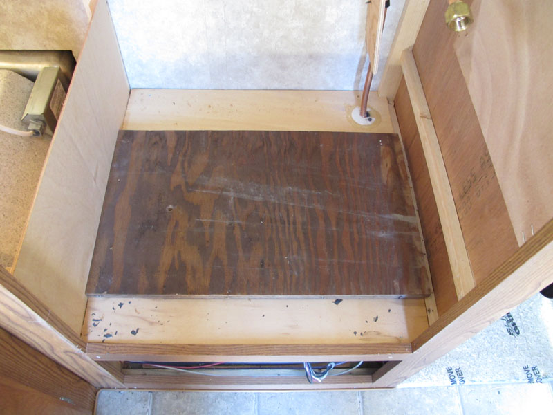
The plywood over the furnace is very thin, so place a scrap piece of plywood over it to sit on. If you use a piece that fills the hole like this, it will have good support.
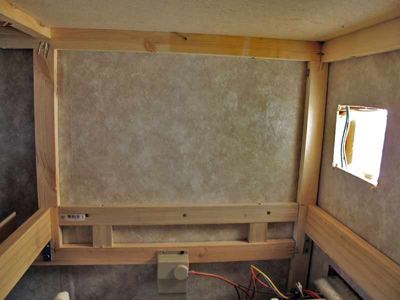
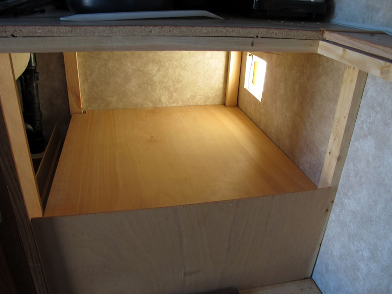
I've added 1x2's and a 1x4's to support the compartment floor. Note how I cut out for the 120VAC line going into the wall. I wanted my compartment floor to be as low as possible.
A straight-on photo of the outside wall floor support
The forward floor support
The inside floor suport
Another general view of the floor supports.
Once last chance to see the floor supports
A 2 'x 2'x 7/16" makes the floor after being trimmed to fit.
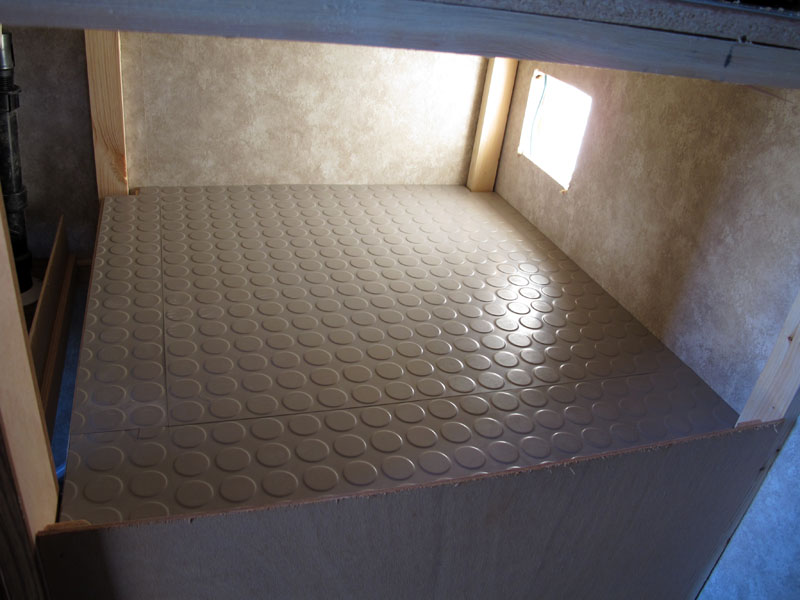
The folks that bought our motorhome sold commercial flooring and gave us an assortment of flooring materials. Here is some very heavy duty flooring made by Pirelli. Too bad no one will ever see it.
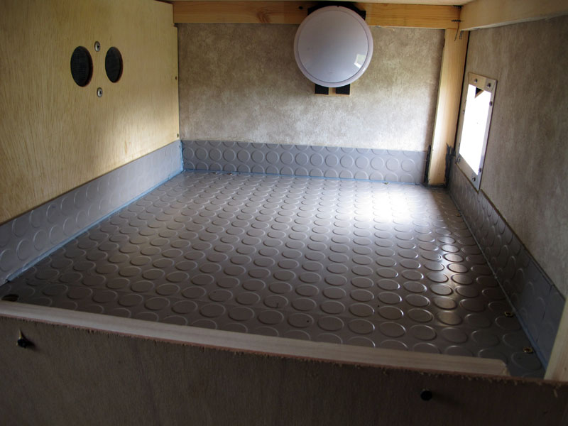
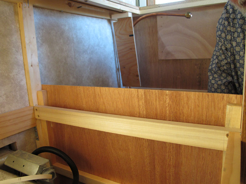
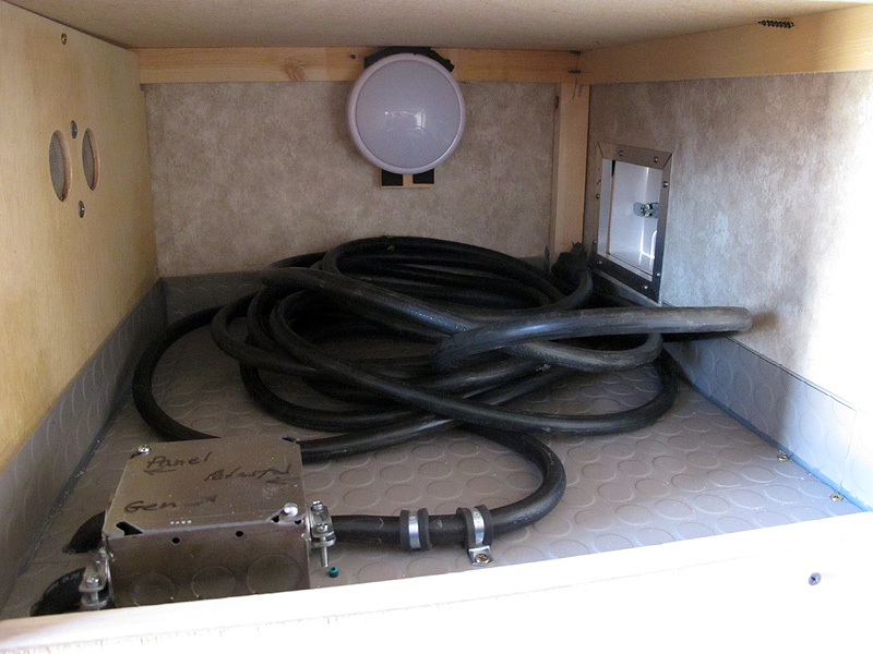
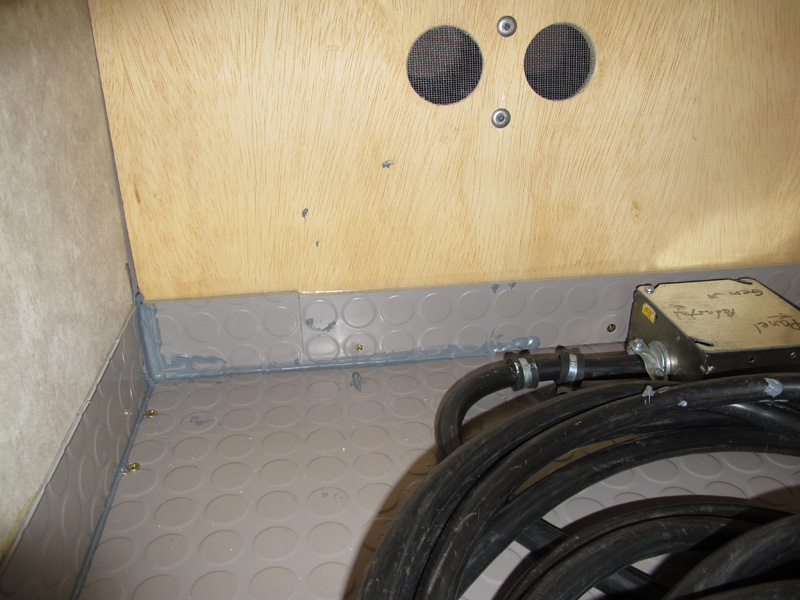
The inside wall is installed, as well as a 2.5" high base board of the Pirelli flooring. The seams have been caulked so that water from a wet cord won't get into things and it will be tough for bugs & other critters to get into the coach via the shore power cord. I added some screens for ventilation.
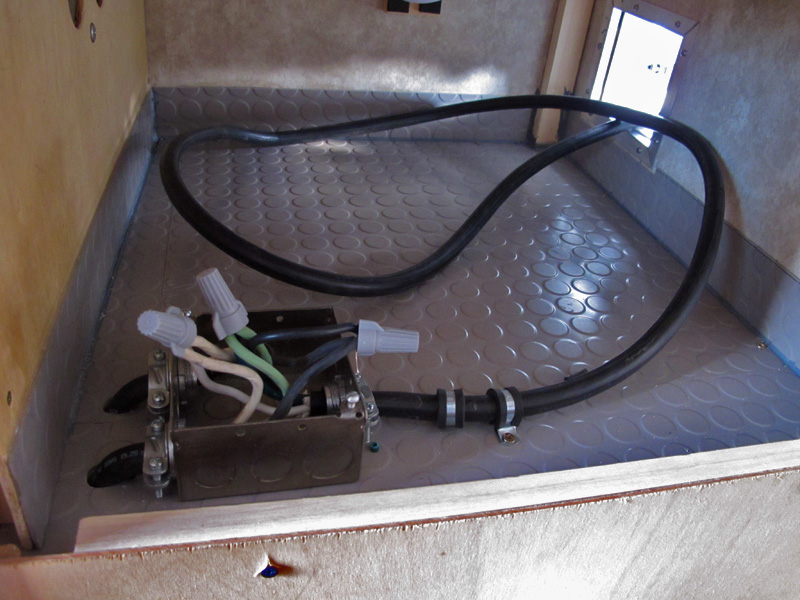
The electrical box is partially installed.
Almost finished! Notice how easily the shore power cable fits into the new compartment? Also notice how there are two cables running from the box through the floor into the coach. The far one goes to the Progressive EMS Input. The near cable goes to the future generator installation. Someday, I might get fancy and install an automatic transfer switch, but that does seem like a little overkill for a Honda 2000i. Maybe, if we upgrade to an electric start Honda 3000i.
I've backed my way out of the compartment by pulling the last wall into place. There is a 3/4" X 3/4" strip of wood at the bottom that's screwed to the wall and to the compartment floor plus the two short pieces of wood at the top. Yes, it was a bit tricky getting it into place.
I had to caulk the last joint by Braille, so the caulking gun hit a few things it wasn't supposed to.
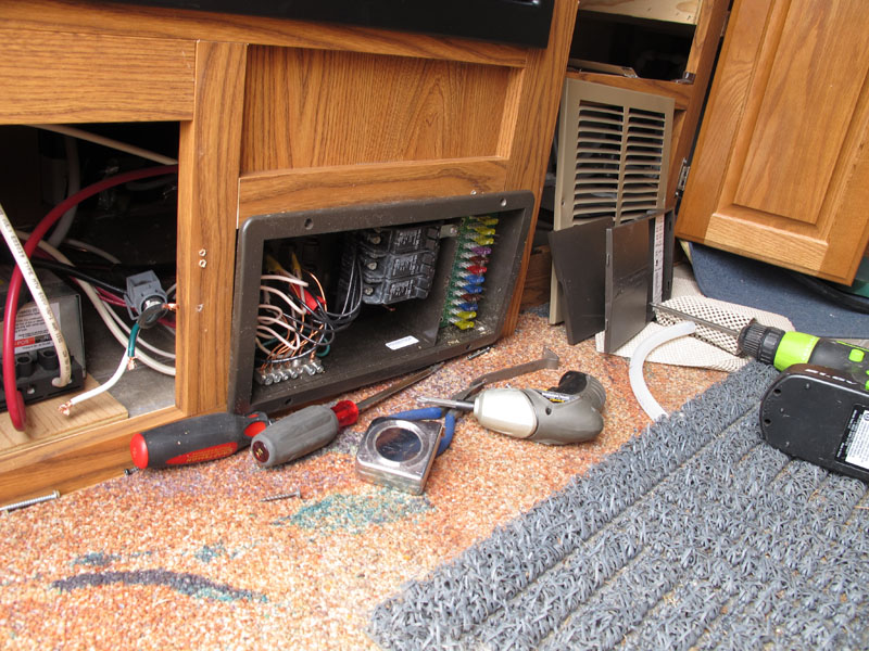
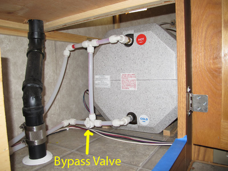
Actually, this photo was taken much earlier when the shore power cable was disconnected from the distribution panel. You can see the end of the shore power cable in the gray bulkhead fitting to the left. For those that are unfamilar with the Arctic Fox 24-5N, the refer is above the electrical distribution panel.
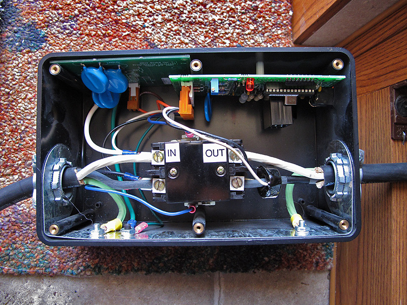
One of the first things we do to every RV we own is to install a hardwired EMS system. This is our Progressive 30A EMS with the cover off. I've got the EMS out of the cabinet & on the floor to make it easy to make the connections.
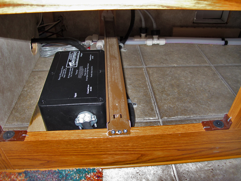
The Progressive EMS fits under the galley drawers like a penny in a gum machine. Note how it is right next to the drawer track so the sides of the drawer don't hit it. Also, note that the EMS is mounted on a 3/8" thick piece of plywood to keep it dry. The electrical distribution panel & refer are to the left and you can see the original shore power access door in the upper right of this photo.
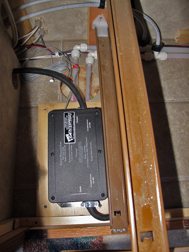
An overhead view of the Progressive EMS.
More on the Progressive EMS later.
Now, it's time to install the new access door. First, I ripped a 1x3 down to 1 9/16" to fill the gap between the inside and outside walls.
A single countersunk deck screw through the inside wall hold each piece of wood in place.
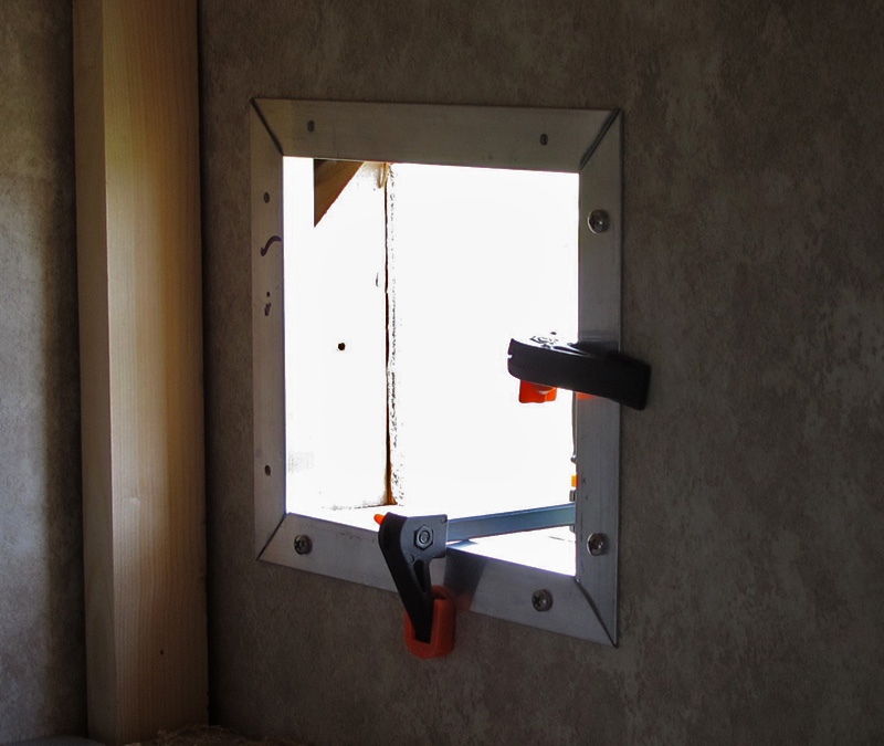
Some aluminum trim finishes off the inside of the cutout.
The cutout with the aluminum trim in place and ready for the new access door.
Eight stainless steel screws hold the access door in place. The screws have well over 1.5" of material to grab with the wood inserts in the wall. The door is caulked with white silicone.
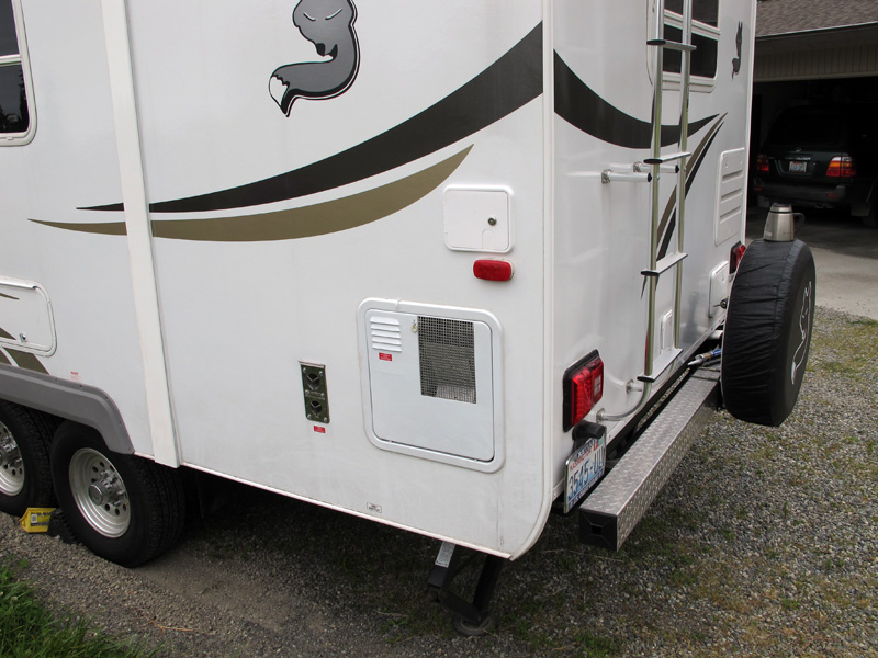
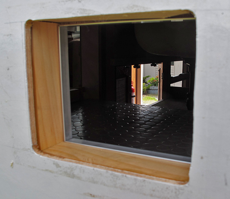
The finished shore power compartment from the outside.
Now, I went back & installed the remote for the Progressive EMS. It would have been easy to mount the remote on the wood panel just above the power distribution box, however it would have been difficult to read the display while standing, so I decided to make a tilted panel for the remote.
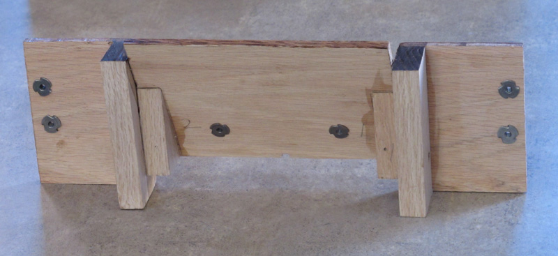
This is the rear view of the tilted panel. I'm more of a wood butcher than an artisan, so it's a bit cruder than it could be, but it's Hell for strong and strong is good. Each piece is both glued & screwed together. Note the blind nut for the remote in the center panel and the two at each end for mounting in the cabinet.
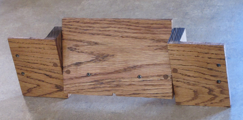
A front view of the panel after staining "Golden Oak', but before varnishing.

Three coats of spray Minwax Fast-Drying Polyurethane semi-gloss
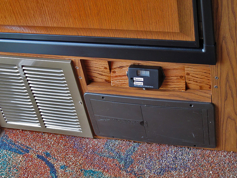
The completed panel installed. I'll touch up the panel mounting screws with paint rather than plugging them. I like to be able to take things back apart as easily as possible.
The Progressive EMS remote cycles through 4 readouts during normal operation:
 Voltage coming into the coach: 126 VAC
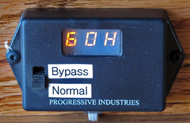 Hertz: 60 Hertz
 Amperage being used: 0 Amps
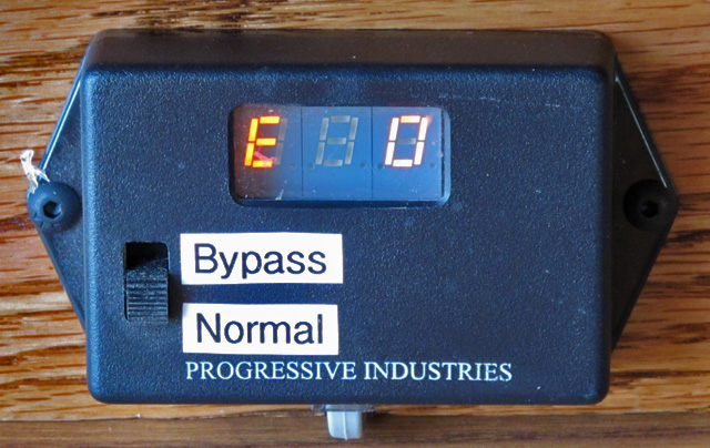 Error Code: Error "0" means 'No Errors'